Refrigeration Rack System Piping Diagram
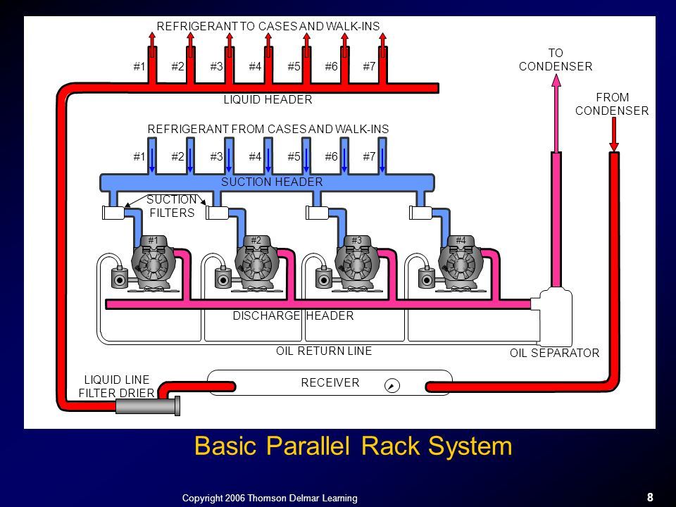
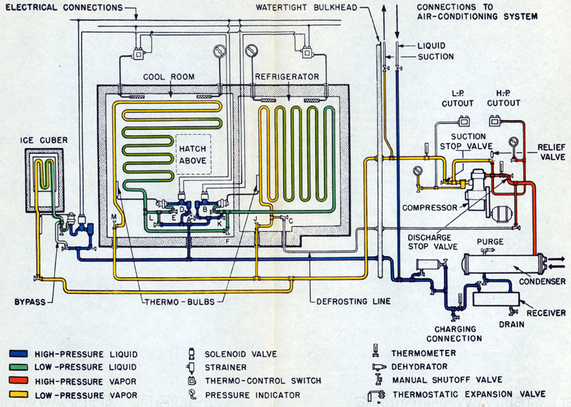
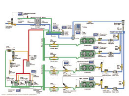
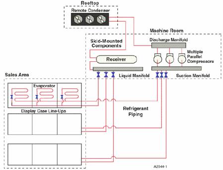
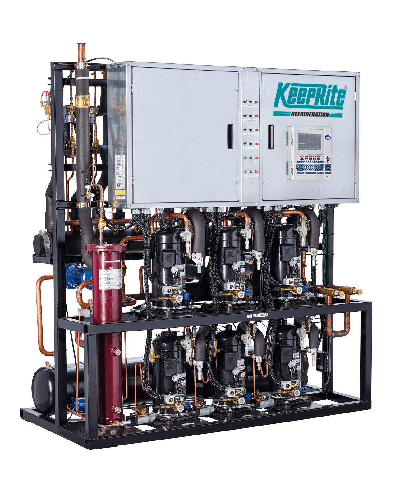
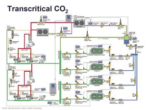
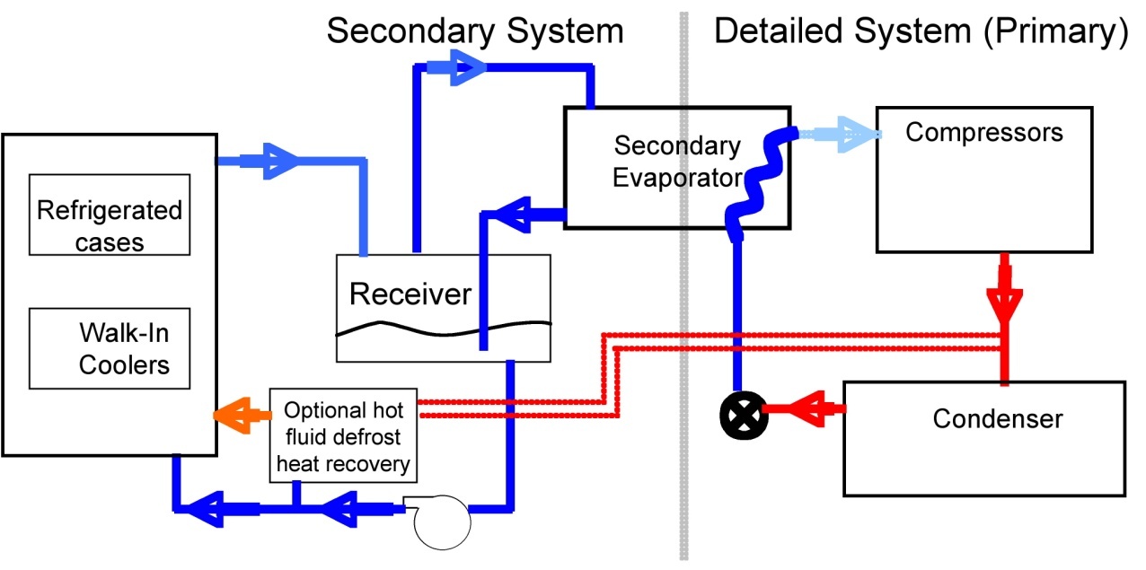
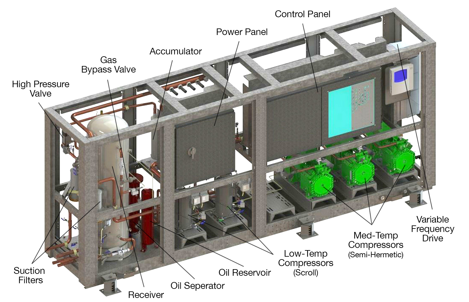
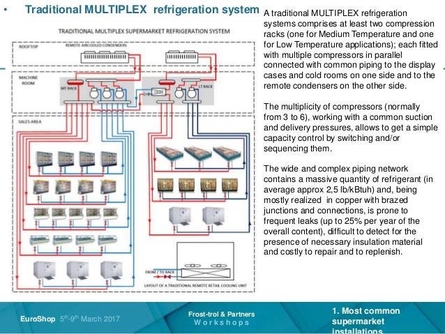
Refrigeration rack system piping diagram. Whether youre using walk-in coolers freezers merchandisers or prep tables a refrigeration rack system that moves compressors outside your commercial kitchen can help. The item numbers in this procedure correspond with the Figure 1 drawing on page 24-9. The Zero Zone production approach minimizes pipe.
Velocities in horizontal lines should be at least 750 ftmin. Large Diameter Riser 4395 cm2 1997 cm 2398 cm2 Using Table 12 we see that 3717 square inches is between a. The small equalizer line from the receiver to the inlet piping of the condenser should have a valve for shutting off the receiver.
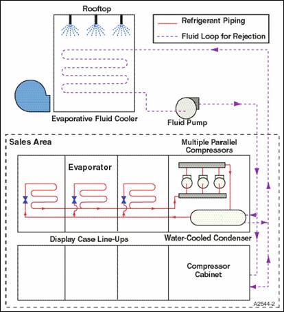
2013 Sporlan Division Parker Hannifin Corporation Form 5-180-32013. The size of this pipe can be 38 up to 25 tons capacity and 12 up to 60 tons. Determine the locations of both the evaporator and condenser sections within the structure and which section contains the compressors.
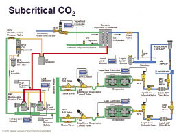
Evaporators Check Valve Check Valve. In the background is the pressure - enthalpy p-h chart for a HFC refrigerant. Demonstrate certain demands that the piping design must meet.
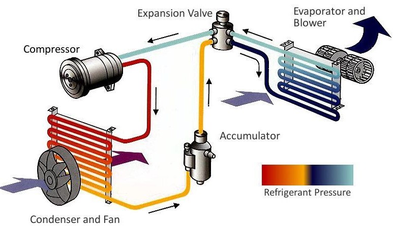
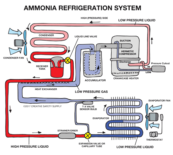
Figure 1-3 shows the cycle for a basic HFC refrigeration system. DX racks check and insure that the correct rack is located on the nominated system platform designated area. Do not apply any power supply to the compressors unless all suction discharge shut off service valves are opened.
This document reviews standard hot gas defrost piping diagrams for recirculated controlled pressure receiver CPR direct expansion and gravity flooded evaporator systems. The critical point occurs at 878F which is below typical system condensing temperatures for part or all of the year depending on the climate. Above this point the refrigerant is not considered liquid or gas but an undefined fluid.
This clinic focuses on systems that use Refrigerant-22 R-22. R22 PH Diagram Diagram created using REFPROP NIST Reference Fluid Properties As can be seen the critical point of R-22 is more than 200F placing it well above the operating conditions of typical refrigeration systems.
The pink indicates the high pressure side and the blue the low pressure side The numbers on the diagram relate to the refrigerant state explained below.
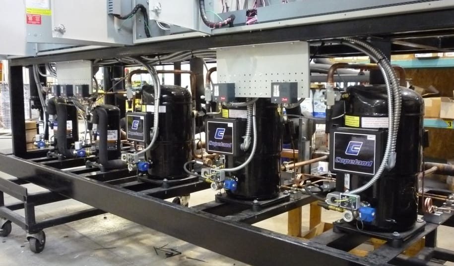
Youre ready to do something about it and it starts with remote refrigeration and a rack system. To handle these pressures piping needs to. When a flooding valve is not used the minimum distance from the base of the rack to the mounting surface of the condenser is 45 ft. To expand into Parallel Rack Refrigeration work is a bold brave move by anyone. Cleanliness of all refrigeration piping is of the utmost importance in the installation procedure. There is no phase change. The following procedure must be followed for each installation at the time of system start-up to properly adjust the SPR. Youre ready to do something about it and it starts with remote refrigeration and a rack system. Whether youre using walk-in coolers freezers merchandisers or prep tables a refrigeration rack system that moves compressors outside your commercial kitchen can help.
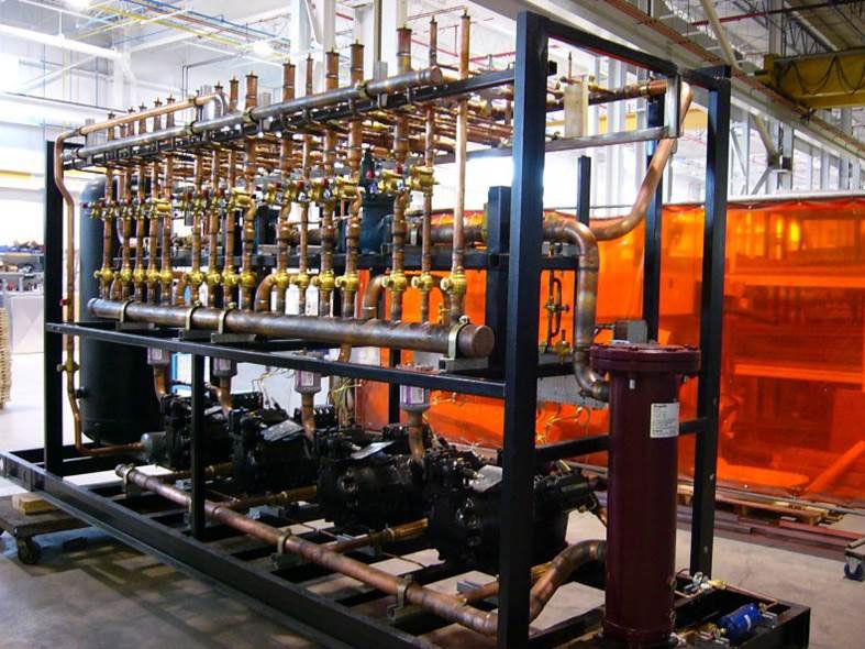
Good refrigeration piping design requires that the refrigeration lines be pitched in the direction of flow at approximately 12 inch per 10 feet or 1 inch per 20 feet. The small equalizer line from the receiver to the inlet piping of the condenser should have a valve for shutting off the receiver. If roof mounted place on column-supported beams or load- bearing walls. Interconnecting pipework engineered to application Ball valves for servicing the rack and or system. One of the major advantages of a Zero Zone Parallel Rack System is its long-lasting durability. Determine the locations of both the evaporator and condenser sections within the structure and which section contains the compressors. Large Diameter Riser 6812 inch2 3095 inch 3717 inch2.
















Post a Comment for "Refrigeration Rack System Piping Diagram"